| |
|

|
|
|
|
|
|
|
|
|
|
|
|
|
|
|
|
|
|
|
|
|
|
|
|
|
|
|
| |
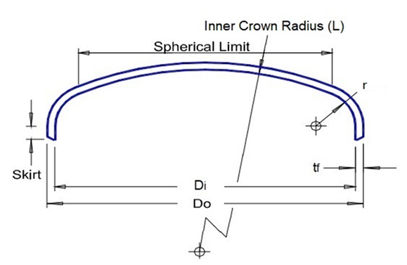
Wall
Thickness Calculation of Torispherical Head Under Internal Pressure
|
| |
| |
ASME
Section VIII Div 1 - UG-32 - Formed Heads, and Sections, Pressure on Concave
Side
|
| |
UG-32(d)
Torispherical Heads with ts /L ≥ 0,002
|
|
|
| |
|
|
| |
|
(Enter values in yellow cells for calculations)
|
| |
DATA INPUT
|
| |
|
|
|
|
|
|
|
|
|
|
|
|
|
|
|
|
|
|
|
|
|
|
|
|
|
|
|
|
| |
|
Design Conditions
|
|
|
Material
|
|
|
|
| |
|
Design Pressure, Pd =
|
|
barg
|
Head
Material Specification (1 to 7)
|
|
|
|
| |
|
|
|
|
|
|
|
|
|
|
|
|
|
|
|
|
|
|
|
|
|
|
|
|
|
|
|
|
| |
|
Design Temperature, Td =
|
|
°C
|
Allowable
Stress Head (8),
S =
|
|
MPa
|
|
| |
|
|
|
|
|
|
|
|
|
|
|
|
|
|
|
|
|
|
|
|
|
|
|
|
|
|
|
|
| |
|
Welding Efficiency, E =
|
|
|
Dimensions
|
|
|
|
| |
|
See Table UW-12
|
|
|
Inside
diameter of the head skirt, Di =
|
|
mm
|
|
| |
|
Corrosion Allowance, CA =
|
|
mm
|
|
|
|
|
|
|
|
|
|
|
|
|
|
|
|
|
|
|
|
|
|
|
|
|
| |
|
|
|
|
Nominal wall
thickness before forming (9), tn =
|
|
mm
|
|
|
|
|
|
|
|
|
|
|
|
|
|
|
|
|
|
|
|
|
|
|
|
|
|
|
|
|
|
|
| |
|
|
|
|
Minimum
specified thickness after forming (10), tf =
|
|
mm
|
|
| |
|
|
|
|
Minimum
required thickness after forming, tr =
|
|
mm
|
|
| |
|
|
|
|
|
|
|
|
|
|
|
|
|
|
|
|
|
|
|
|
|
|
|
|
|
|
|
|
| |
|
|
|
|
Outside
diameter of the head skirt, Do =
|
|
mm
|
|
| |
|
|
|
|
|
|
|
|
|
|
|
|
|
|
|
|
|
|
|
|
|
|
|
|
|
|
|
|
| |
|
|
|
|
Inside
knuckle radius is 6% of the inside crown radius (11), r =
|
|
mm
|
|
|
|
|
|
Check inside knuckle radius is in no case less than 3 times the
head thickness (t)
|
|
|
|
|
|
|
|
|
|
|
|
|
|
|
|
|
|
|
|
|
|
|
|
|
|
|
|
|
|
|
|
|
| |
|
|
|
|
Straight skirt length (12)(13), SK =
|
|
mm
|
|
| |
|
|
|
|
|
|
|
|
|
|
|
|
|
|
|
|
|
|
|
|
|
|
|
|
|
|
|
|
| |
|
|
|
|
Check If tr
≤ tn
|
|
|
|
| |
|
|
|
|
Check If tr
≤ tf
|
|
|
|
| |
|
Notes:
|
|
|
|
|
|
|
|
|
|
|
|
|
|
|
|
|
|
|
|
|
|
|
|
|
|
|
| |
(1)
|
S ≤ 66.66% of σy @ temp.
|
|
|
|
|
| |
(2)
|
S > 66.66% but < 90% of σy @ temp.
|
|
|
|
|
| |
(3)
|
t ≤ 65
|
|
|
|
|
| |
(4)
|
65 < t ≤ 100
|
|
|
|
|
| |
(5)
|
100 < t ≤ 150
|
|
|
|
|
| |
(6)
|
Tensile strength of
the Section IX reduced section tension test is not less than 690 MPa.
|
|
|
|
|
| |
(7)
|
Tensile strength of
the Section IX reduced tension test less than 690 MPa but not less than 655
MPa.
|
|
|
|
|
| |
(8)
|
As per UG-32(d)
Torispherical heads made of materials having a specified minimum tensile
strength exceeding 70,000 psi (485 MPa) shall be designed using a value of S
equal to 20,000 psi (138 MPa) at room temperature and reduced in proportion
to the reduction in maximum allowable stress values at tempera ture for the
material as shown in the appropriate table (see UG-23).
|
|
| |
(9)
|
It is recommended a nominal thickness before
forming 15% higher than the minimum specified thickness to ensure after
forming thickness is above it.
|
|
| |
(10)
|
As per UG-79 (d)(3)
The reduction in weld thickness after forming shall not exceed 1/32 in. (1
mm) or 10% of the nominal thickness of the adjoining surface, whichever is
less.
|
|
| |
(11)
|
As per UG-32
(i) The inside crown radius to which
an unstayed head is dished shall be not greater than the outside diameter of
the skirt of the head. The inside knuckle radius of a torispherical head
shall be not less than 6% of the outside diameter of the skirt of the head
but in no case less than 3 times the head thickness.
|
|
| |
(12)
|
As per UG-32(k) All
formed heads, thicker than the shell and concave to pressure, intended for
butt welded attachment, shall have a skirt length sufficient to meet the
requirements of Figure UW-13.1, when a tapered transition is required. All
formed heads concave to pressure and intended for butt welded attachment need
not have an integral skirt when the thickness of the head is equal to or less
than the thickness of the shell. When a skirt is provided, its thickness
shall be at least that required for a seamless shell of the same inside
diameter.
|
|
| |
(13)
|
As per UG-32(l)
Heads concave to pressure,intended for attachment by brazing, shall have a
skirt length sufficient to meet the requirements for circumferential joints
in Part UB.
|
|
| |
|
|
|
|
|
|
|
|
|
|
|
|
|
|
|
|
|
|
|
|
|
|
|
|
|
|
|
|
| |
|
|
|
|
|
|
|
|
|
|
|
|
|
|
|
|
|
|
|
|
|
|
|
|
|
|
|
| |
CALCULATIONS
|
| |
|
|
|
|
|
|
|
|
|
|
|
|
|
|
|
|
|
|
|
|
|
|
|
|
|
|
|
|
| |
|
Torispherical Head
|
|
|
|
|
|
|
|
|
|
|
|
|
|
|
|
|
|
|
|
|
|
|
|
|
|
|
| |
|
with tf/L ≥ 0.002
|
|
|
|
|
|
|
|
|
|
|
|
|
|
|
|
|
|
|
|
|
|
|
|
|
|
|
| |
|
Thickness after forming adjusted for corrosion, nt =
|
|
mm
|
|
nt = tf-CA
|
|
|
|
|
|
|
|
|
|
|
|
|
|
|
|
|
|
|
| |
|
|
|
|
|
|
|
|
|
|
|
|
|
|
|
|
|
|
|
|
|
|
|
|
|
|
|
|
| |
|
Inside spherical or crown radius adjusted for corrosion, Lc (14) =
|
|
mm
|
|
Lc = Do + CA
|
|
|
|
|
|
|
|
|
|
|
|
|
|
|
|
|
|
|
| |
|
|
|
|
|
|
|
|
|
|
|
|
|
|
|
|
|
|
|
|
|
|
|
|
|
|
|
|
| |
|
Inside knuckle radius, r =
|
|
mm
|
|
|
|
|
|
|
|
|
|
|
|
|
|
|
|
|
|
|
|
|
|
|
|
|
| |
|
|
|
|
|
|
|
|
|
|
|
|
|
|
|
|
|
|
|
|
|
|
|
|
|
|
|
|
| |
|
Wall Thickness [UG-32(d)]
|
|
|
|
|
|
|
|
|
|
|
|
|
|
|
|
|
|
|
|
|
|
|
|
|
|
|
| |
|
Minimum required thickness after forming, t =
|
|
mm
|
|
t =
|
0.885 P Lc
|
|
|
|
|
|
|
|
|
|
|
|
|
|
|
|
| |
|
|
|
|
|
S E - 0.1 P
|
|
|
|
|
|
|
|
|
|
|
|
|
|
|
|
| |
|
|
|
|
|
|
|
|
|
|
|
|
|
|
|
|
|
|
|
|
|
|
|
|
|
|
|
|
| |
|
Minimum required thickness after forming, tr =
|
|
mm
|
|
tr =
|
0.885 P Lc
|
+ CA
|
|
|
|
|
|
|
|
|
|
|
|
|
| |
|
|
|
|
|
S E - 0.1 P
|
|
|
|
|
|
|
|
|
|
|
|
|
| |
|
|
|
|
|
|
|
|
|
|
|
|
|
|
|
|
|
|
|
|
|
|
|
|
|
|
|
|
| |
|
Check If tr ≤ tf
|
|
|
|
|
|
|
|
|
|
|
|
|
|
|
|
|
|
|
|
|
|
|
|
|
|
|
| |
|
|
|
|
|
|
|
|
|
|
|
|
|
|
|
|
|
|
|
|
|
|
|
|
|
|
|
|
| |
|
Maximum allowable working pressure [UG-32(d)]
|
|
|
|
|
|
|
|
|
|
|
|
|
|
|
|
|
|
|
|
|
|
|
|
|
|
|
| |
|
Maximum allowable working pressure for Torispherical Head,
MAWP =
|
|
barg
|
|
MAWP =
|
S E nt
|
|
|
|
|
|
|
|
|
|
|
|
|
|
| |
|
|
|
|
|
0.885 Lc + 0.1 nt
|
|
|
|
|
|
|
|
|
|
|
|
|
|
| |
|
|
|
|
|
|
|
|
|
|
|
|
|
|
|
|
|
|
|
|
|
|
|
|
|
|
|
|
| |
|
Check If MAWP ≥ P
|
|
|
|
|
|
|
|
|
|
|
|
|
|
|
|
|
|
|
|
|
|
|
|
|
|
|
| |
|
|
|
|
|
|
|
|
|
|
|
|
|
|
|
|
|
|
|
|
|
|
|
|
|
|
|
|
| |
|
Check
|
|
|
|
|
|
|
|
|
|
|
|
|
|
|
|
|
|
|
|
|
|
|
|
|
|
|
| |
|
Limitations: tf/L ≥ 0.002
|
|
|
|
|
|
|
|
|
|
|
|
|
|
|
|
|
|
| |
|
|
|
|
|
|
|
|
|
|
|
|
|
|
|
|
|
|
|
|
|
|
|
|
|
|
|
|
| |
|
Inside Volume =
|
|
m³
|
|
V
=
|
(
|
0.0847
Di³
|
+
|
π Di² SK
|
)
|
/ 10⁹
|
|
|
|
|
|
|
|
|
| |
|
|
|
|
|
4
|
|
|
|
|
|
|
|
|
| |
|
|
|
|
|
|
|
|
|
|
|
|
|
|
|
|
|
|
|
|
|
|
|
|
|
|
|
|
| |
|
Weight =
|
|
Kg
|
|
W
=
|
((
|
0.0847
(Do³-Di³)
|
+
|
π (Do²-Di²) SK
|
)
|
/ 10⁹)
ρm
|
|
|
|
| |
|
|
|
|
|
4
|
|
|
|
| |
|
|
|
|
|
|
|
|
|
|
|
|
|
|
|
|
|
|
|
|
|
|
|
|
|
|
|
|
| |
|
Note:
|
|
|
|
|
|
|
|
|
|
|
|
|
|
|
|
|
|
|
|
|
|
|
|
|
|
|
| |
(14)
|
As per UG-32(d) the
inside crown radius shall be equals the outside diameter of the skirt [see
UG-32(i)]
|
|
| |
|
|
|
|
|
|
|
|
|
|
|
|
|
|
|
|
|
|
|
|
|
|
|
|
|
|
|
|
| |
|
|
| |
RESULT
|
| |
|
|
|
|
|
| |
|
Design Conditions
|
|
|
|
|
|
| |
|
Design Pressure, Pd =
|
|
barg
|
|
|
| |
|
Design Temperature, Td =
|
|
°C
|
|
|
| |
|
|
|
|
|
|
| |
|
Material
|
|
|
|
|
| |
|
Head Material
|
|
|
|
|
| |
|
|
|
|
|
|
| |
|
Dimensions
|
|
|
|
|
| |
|
Outside diameter of the head skirt, Do =
|
|
mm
|
|
|
| |
|
Nominal wall thickness before forming, tn =
|
|
mm
|
|
|
| |
|
Thickness after forming, tf =
|
|
mm
|
|
|
| |
|
Inside spherical or crown radius, L =
|
|
mm (L = Do)
|
|
|
| |
|
Inside knuckle radius, r =
|
|
mm
|
|
|
| |
|
|
|
|
|
|
| |
|
Maximum allowable working pressure, MAWP =
|
|
barg
|
|
|
| |
|
Inside Volume =
|
|
m³
|
|
|
| |
|
Weight =
|
|
Kg
|
|
|
| |
|
|
|
| |
|
|
|
|
|
|
|
|
|
|
|
|
|
|
|
|
|
|
|
|
|
|
|
|
|
|
|
|
| |
|
|